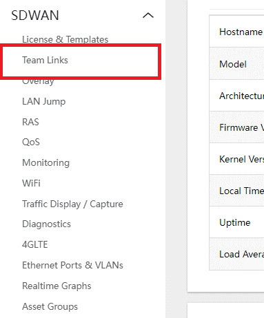
- Navigate to SWAN > TEAM LINKS
- Under the LINK1 section:
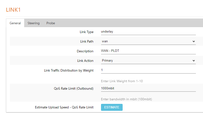
- LINK PATH – Select the INTERFACE the user wants to assign to LINK 1 (ex. WAN,WAN2,4G LTE,MyFi2G,MyFi5G)
- Description – used to be edited accordingly and give the user a hint of the ISP used for the LINK1 Path (ex. WAN – Spectrum)
- LINK ACTION – select whether the LINK should be a PRIMARY LINK or BACKUP LINK. The user also has an option to DISABLE the link.
- LINK TRAFFIC DISTRIBUTION BY WEIGHT – edit as user desires. This assigns the traffic weight to pass on the link.
- QOS RATE LIMIT – used to limit the OUTBOUND BANDWIDTH of the Link.
- ESTIMATE UPLOAD SPEED – This action will disable Link1 QoS, do a Speedtest on the Link and give an upload speed result which can be used for the QOS RATE LIMIT.
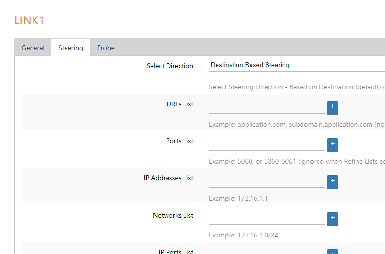
- Under the Steering Tab, the user can add the Urls, Ports, etc. that is desired to be steered to LINK1 specifically.
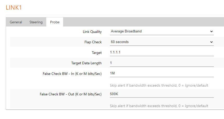
- Under the probe tab:
- LINK QUALITY – This is the ‘PROFILE’ that sets the sensitivity of the Link for failover. Usually used to desensitize the probes if the site has Internet connection issues.
- FLAP CHECK – when failed over to BACKUP LINK, the device will check for LINK 1 connectivity. If LINK1 passes the check for duration set in FLAP CHECK, the device will failback to the PRIMARY LINK.
- TARGET – IP used to send probe packets.
- FALSE CHECK BW – this prevents failover false positives during high bandwidth usage. Set in K in kbits/sec or M mbits/sec (ex. 1M IN and 100K OUT).
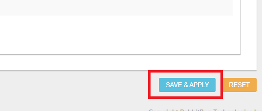
- Click on SAVE AND APPLY at the bottom of the page to save changes made.